
BSI/JTAG Test Platform (Boundary Scan Test Platform) / R&D Tools / MIS
BSI/JTAG Test Platform (Boundary Scan Test Platform)
The platform contains Test & Repair, PLD Configuration/Programming and Flash Programming modules.
This platform uses JTAG plug/header of your card, so no extra interface is needed. The platform can detect manufacturing issues, and can be used as a debug tool. PLD Configuration/Programming module supports multi vendors' devices. Flash Programming module runs without simulators/emulators. You could select Flash devices without sockets since we can program Flash in-circuit (on board) directly. It's easier to use , because none CPU register initialization needed. It's also suitable for mass production.
BSTest: Test & Repair
.png)
The platform supports both automatic tests and manual tests. Tests marked with '*' could be run in batch mode with 'One-Click', or, run background without any interactive operation.
Single Device Test *
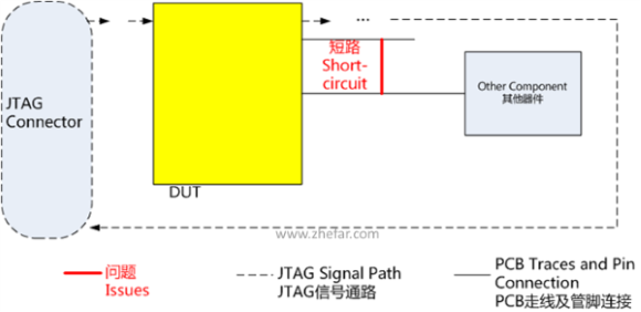 This automatic operation can detect short between pins (in fact, not only pins of JTAG chip, but also pins of other devices connected to JTAG chip), or short between I/O pins and power supply or ground.
Inter-device Test *
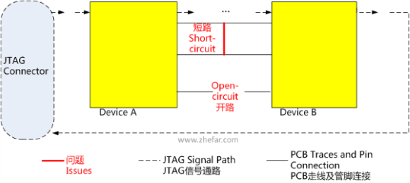 The system reads schematic netlists, and analyzes the device inter-connection, then generates test patterns. Inter-device test can automatically find short (pin to pin, pin to power supply or ground), open and other issues.
Peripheral Test *
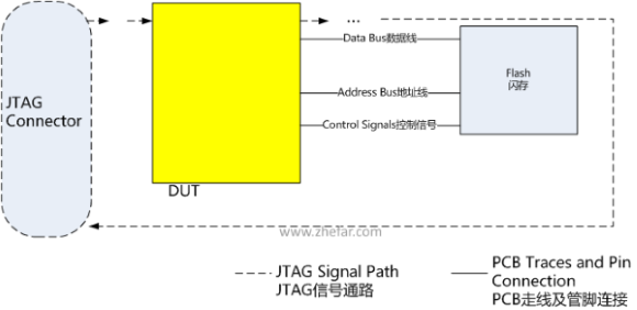 The software could test components connected to JTAG device, such as checking ID of a Flash, testing data bus and address bus of SRAM for open-circuit or short-circuit issues, etc.
Manual Test
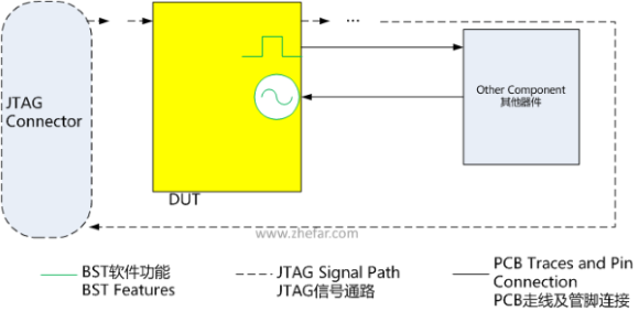 The system can display status of JTAG chip's pins (something like an oscilloscope or logic analyzer), and can control the chip to output a user defined waveform (something like a signal generator). You can find issues in welding (open, short, etc.) or PCB production by analyzing the phenomenon. Also, it can be used as debugging tool.
BSTest: PLD Configuration/Programming
One system to configure PLDs of many vendors.
Currently .svf and .vme files are supported.
Our software platform could configure Altera FPGA under Passive Serial mode with .rbf file, and also support configuring Xilinx FPGA under Slave Serial mode with .bit file. Note: Serial configuration mode is NOT JTAG mode.
BSTTclDll: dll library for secondary development
Besides GUI edition, we provide dll for secondary development. The Tcl source file could be run both interactively in Tcl/Tk shell and completely in console command line. And the Tcl interpreter could be embedded in C/C++/C# and other language programs to be integrated in existent test system.
yaJFPb: JTAG Flash Programmer
.png)
Features
- Don't need the Flash sockets anymore;
- No need to use debuggers or emulators;
- Lightweight green software;
- CPU architecture independent. Supports CPUs based on x86/PowerPC/ARM/MIPS architectures, also supports DSP, NP, CPLD/FPGA and other SoC;
- Support multi devices in JTAG chain;
- Use CPU standard JTAG port, without extra design;
- NO one-line boot code needed. Run without any configuration for clock, SDRAM, etc.;
- Can read Flash data even CPU hangs or Flash data is corrupt;
- 10x times faster than parallel cable when programming with WH-USB-JTAG cable; 5x times faster as WH-USB-JTAG with WH-USB-HiJTAG;
Functions
- Support many vendors' Flash: numonyx, Spansion, Intel, AMD, ST, SST, EON, MXIC, etc.;
- Read, Programming Flash;
- Block operation (erase, lock ,unlock);
- Besides programming, the software can lighten LEDs to verify the JTAG function;
- Read/Write other ICs; The JTAG software can read and write other ICs (e.g., CPLD, ASIC, etc.) connected to the JTAG device (usually the CPU, but other ICs are also OK), so you can debug your card without software running. It will highly enhance the debug efficiency and shorten the time to market.
- Easily integrated with manufacturing automation system: Run specified operations automatically and silently without clicking any button.
- Calculating hash value of programming file based on multiple algorithms. Avoid writing wrong file by comparing calculated value with expected value.
- Support batch programming: Automatically program different file to different address;
- Optimized for whole-chip programming;
EthCfg: MDIO Master Debug Solution
.png)
With a USB cable, you could read/write the MDIO registers of Ethernet PHY on your computer. Support batch reading.
ACompare: Schematic (Netlist) Compare Software
Schematic and PCB files are binary files, so they cannot be compared directly. Our software compares them with netlists, which have all info of the design.
The software not only compares connections, but also compares component packages (PCB footprints).
From the comparison result, you can easily see what difference between the schematics or PCBs.
Besides, this utility could be used to validate schematic / PCB file version when archiving.
ACompare: Other Files Comparing
- BOM File Comparing
- PLD Constraints File Comparing Supports Xilinx ucf, Lattice prp/lci/lpf and Altera qsf format files.
- Location of Components of PCB Comparing
PinLock: PLD Pin Location Constraint File Auto Generating Software
PLDs (CPLD, FPGA, and so on) are widely used now. Pin location is a very important design constraint in PLD design.
To generate the pin location constraint, the engineers have to fill the location in the PLD EDA software one by one--manually watch the schematic design in schematic EDA software window, and then switch to the EDA software window to input them, and then switch back to schematic software window to see next pin location. It's boring. And, it's NOT reliable.
Our software reads pin info from schematic netlist file, then generates PLD pin location constraint file automatically.
- Support Xilinx ucf, Lattice prp/lci/lpf and Altera qsf format files.
- Can sort the constraint file by pin location, or by netlist name.
- Filter non-I/O pins with post processing.
IMS: Instruments Management System
- Based on LAMP (Linux + Apache + MySQL + PHP) OS can be Windows, and Web server can be IIS. No client software installation needed.
- Basic info management Photos could be attached.
- Lend Renewal allowed.
- Booking
- Check
- Daily maintenance Overdue; Blacklist; Export;
- Query
MMS: Material Management System
- Based on LAMP (Linux + Apache + MySQL + PHP) OS can be Windows, and Web server can be IIS. No client software installation needed.
- Basic info management
- Withdraw/Input Support tagging, so our system can distinguish product line and project info.
- Inventory Automatically analyze requirement by checking uploaded BOM file;
- Check
- Query
PON OLT/ONU
EPON OLT
YT-EPL100 is a 1U EPON OLT which meets China Telecom's EPON requirement V2.1.
YT-EPL100 comes with 8 down stream EPON, 4 uplink optical GE ports and 4 10/100/1000Base-T uplink ports. Max 512 ONUs are supported.
Features
- High access bandwidth; 8 PON ports @ 1Gbps;
- Small size and high density; 1U box with 8 uplink and 8 downlink ports;
- Flexible management access; In-band, out-band and serial console;
- Very powerful functions; Supports IGMP proxy, VLAN translation, QinQ, ACL, SLA, QoS and so on;
Main Functions
- Multi authentication method: Automatic, MAC based, or LOID+Password mixed;
- Bi-directional FEC;
- Bi-directional encryption;
- Optical power diagnosing;
- In-band, out-band and serial console management;
- Anti IP/MAC cheating, DOS attack, ARP attack, ICMP attack, BPDU attack, etc.;
- Supports IGMP proxy, VLAN translation, QinQ, ACL, SLA, QoS, Link Aggregation and Broadcast Suppression;
GPON ONU
YT-GSF100 is a GPON ONU which supports data and voice services. It's designed for FTTB and FTTH.
YT-GSF100 supplies several GEMPORT and T-CONT ports. YT-GSF100 supports many LAN modes.
Features
- Support 1.25Gbps (US) / 2.5Gbps (DS) GPON optical interface
- Four 10/100Base-T Ethernet ports
- Two POTS (FXS) ports
- IEEE 802.1d MAC bridge
- IGMP Snooping, Multicast GEMPORT
- QoS: Classify, priority, congestion control algorithm;
- OAM: OMCI remote configuration, local telnet configuration;
- Humanity Design: Optical port can be hidden to prevent the laser from hurting eyes.
EPON ONU
Features
- Support 1.25Gbps (US) / 1.25Gbps (DS) EPON optical interface
- Four 10/100Base-T Ethernet ports
- Two POTS (FXS) ports
- IEEE 802.1d MAC bridge
- IGMP Snooping; IGMP V1, V2; Last member query;
- Port based VLAN: 32K 802.1Q VLAN Entries;
- QoS: Classify, priority, congestion control algorithm;
- Management: Web / CLI Interface; IEEE 802.3ah OAM Feature;
- Upgrade via HTTP/TFTP;
- IP Address: Static, DHCP;
- Humanity Design: Optical port can be hidden to prevent the laser from hurting eyes.
Wireless Solutions
RFID
- Reader
- Fixed Installation
- Handheld / Portable
- Desktop
- Tag
- Active Tag
- TTF(Tag Talk First)
- RTF(Reader Talk First)
- Passive Tag
- Active Tag
FR2000 is a fixed installation, far distance UHF RFID reader.
| Model | FR2000 |
|---|---|
| Electric & Reliability | |
| Power Supply |
|
| Max Power Consumption | < 15W |
| Operating Temperature | -10 °C ~ 50 °C |
| Communication & Management | |
| Tag Identify Speed | 100 tag/second |
| Air Interface Protocol | EPCglobal UHF Class 1 Gen 2 / ISO 18000-6C |
| Max Range | 20m |
| Operating Frequencies | 920 ~ 925 MHz |
| RF Power | +10dBm ~ +30dBm |
| Antenna Interface | 4 × RP-TNC Female |
| Communication & Control Interface | Ethernet; RS-232C; |
| On/Off Signal | 4 × input; 4 × output; |
.jpg)
The functions and features of purchased product depends on the part number and your license. | Specifications subjected to change without notice.
